


Reverse engineering is a process that has been gaining popularity in recent years. It involves going from a physical object, through a process of digitizing, modeling, and sometimes optimization, to a new physical object or an improved version of it. It is no longer associated with the theft of someone else’s intellectual property, but a tool for streamlining design and manufacturing processes. It is reverse engineering that allows us to easily reproduce and replace a worn-out part for which there is no documentation.
It’s reverse engineering that allows us to reduce the implementation time of tools or machines by creating new documentation based on optimized parts and components. It is reverse engineering that makes it possible to increase production by quickly reconstructing and improving existing machines.
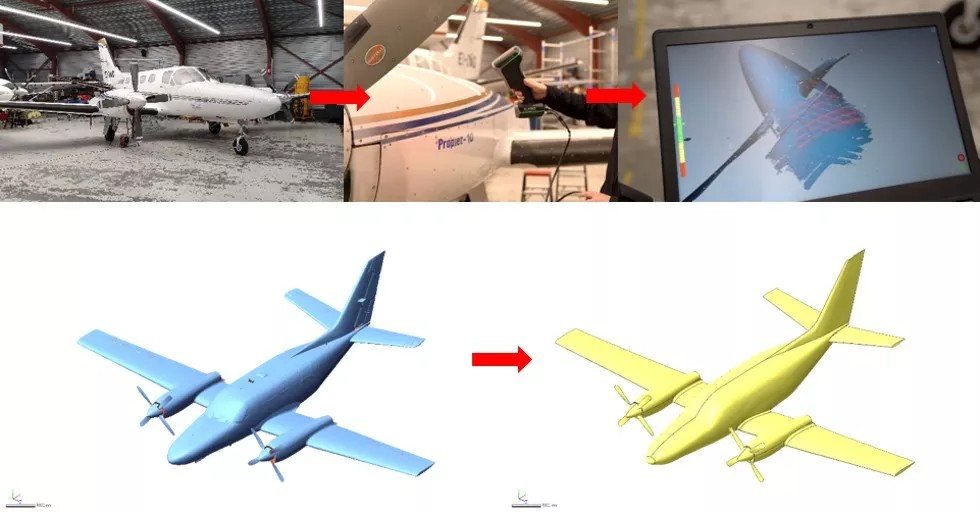
Reverse engineering process of a Cessna 441 aircraft made for aerodynamic optimization
When is reverse engineering required?
Then, what are the main goals of reverse engineering and how to create a functional parametric model on the basis of a physical object? We will try to answer this question in the following article.
Reverse engineering goals:
- reconstructing old parts and part assemblies without documentation
- creating models of new parts without documentation before first assembly
- obtaining documentation of parts during machine downtime
- adaptive design – designing in a real-world environment
- reproduction, modernization and optimization of machines and production lines
- reproduction of modified or optimized tools and prototypes
- digitization of designer’s conceptual design
- archiving of cultural, infrastructure, historical objects
Stages of reverse engineering
The reproduction of real objects in digital space can be divided into several stages:
- data acquisition and analysis – 3D scanning of the physical product
- processing and elaboration of the acquired data
- mechanical modeling or automatic modeling
- verification of the created model
- optimization and modernization of the created model (if needed)
- manufacturing and implementation of the new product
3D Scanning
The first and most important stage of reverse engineering, on which the quality of the final result, as well as the designer’s workload depends, is the acquisition of reliable data describing the object to be reproduced. These can, of course, be obtained with a simple caliper and a sheet of paper, but a far better and more accurate method is the use of a 3D scanner, which is able to very quickly reproduce virtually any thing, of any complexity, with dimensions ranging from a few tens of millimeters to several meters. The result of 3D scanning is a precise mesh of STL triangles.
Today’s handheld 3D laser scanners, such as those manufactured by SCANTECH, are mobile, versatile and professional tools, with metrological accuracies of 0.02mm and high resolution, which allow to create precise 3D data of any object, in any location.
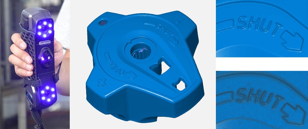
Detail of the 3D scan of the knob, digitized with the SCANTECH SIMSCAN42 3D scanner
The innovative handheld 3D scanner SCANTECH KSCAN Magic also has a patented technology for integrating a photogrammetric system in the scanning head, thanks to which we get the possibility of stable and accurate measurement of large objects. This is a huge advantage in the case of 3D measurements of machinery, vehicles or production lines, when we don’t need to have information about repetitive areas of the measured object, but only about important places, and we want to have everything in one coordinate system. The use of photogrammetric measurement increases 3D data quality, reduces measurement time and amount of used consumables.
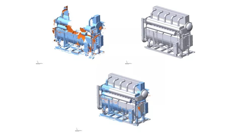
Reverse engineering of a 6x5m heat pump based on incomplete scanning results made with SCANTECH KSCAN Magic
A 3D scanner that is ideal for 3D scanning of vehicles and their cargo space, such as for special body design, is the SCANTECH TRACKSCAN, which does not require reference markers, significantly reducing the time to prepare an object for 3D measurement.
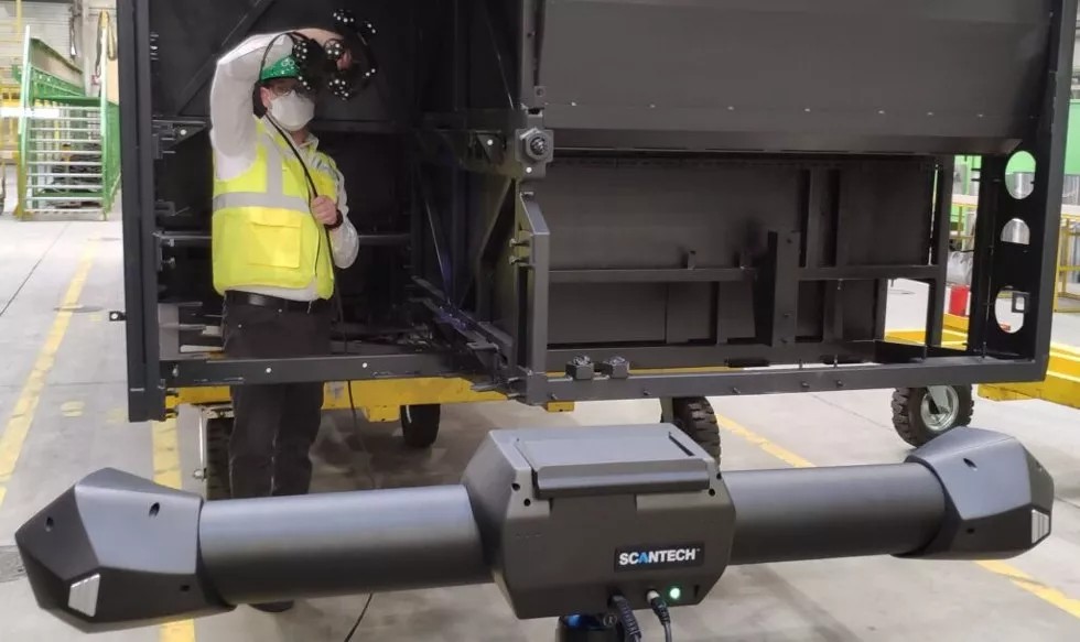
3D measurement of a welded structure using the SCANTECH TRACKSCAN pointless 3D scanner
Today, 3D scanners, as well as the services performed with them, are affordable and accessible to anyone interested in the highest quality data.
Data processing
The result of 3D scanning is a digital model of the measured object saved as an STL triangle mesh. The 3D data provided by a high-end 3D laser scanner most often needs no special processing and can be immediately used for modeling. However, there are times when the mesh needs to be thinned in order to operate more efficiently on a large amount of data, to smooth out surface imperfections or close holes left by under-scanned areas, which is especially important in the case of automatic modeling, the so-called autosurface, during which every deficiency will be included in the final model and prolong its achievement.
An extremely important part of preparing the data for the modeling process is correct alignment of the object in the XYZ coordinate system. This will allow us to easily change the view of the model, as well as perform mirror or rotation operations.
CAD modeling
CAD model creation can be divided into two types mechanical (parametric) and automatic (autosurface). An excellent tool for modeling with both methods is GeoMagic Design X, which has extensive automatic modeling support features, as well as a full project tree that allows you to edit each operation. It also allows you to work on several triangle meshes simultaneously.
Mechanical modeling involves the structural reproduction of a scanned object. The model is generated using sections, extractions, extrusions, constraints, Boolean operations and other methods known from traditional CAD programs. GeoMagic Design X software allows you to perform all construction operations using STL data directly, including performing surface modeling. It automatically captures information about geometric primitives, axes, angles, lengths or radii, significantly streamlining the process of creating the final model.
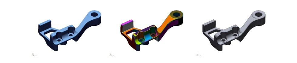
Reverse engineering of the cantilever using regions
A huge advantage of this software is the full tree of operations, which makes the entire project parametric, allowing us to edit and modify every element created. When modeling mechanically or surface, we have an influence on everything that happens, so we can use unscanned data, and we can easily reproduce items that are worn or have cavities. In addition, it is possible to export the created model, along with the entire tree of operations, to native formats such as SolidWorks, SolidEdge, Inventor, NX or Solidedge.
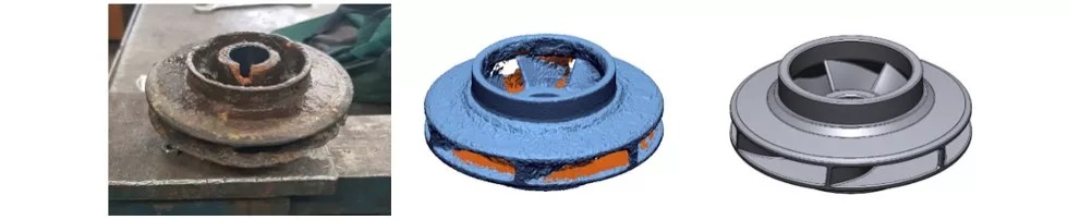
Reverse engineering of a worn rotor
Another way of modeling is autosurface mode, in which GeoMagic Design X automatically recognizes and divides the scanned object into regions where it creates parametric surfaces using the set parameters. The advantage of autosurface is that we can easily recreate complex free surfaces. The disadvantage, on the other hand, is the need to have good quality data with no deficiencies, since the algorithm cannot predict whether a given surface imperfection should be described mathematically or is simply a flaw to be ignored. This mode is ideal for creating models of sculptures, industrial design, or monuments.
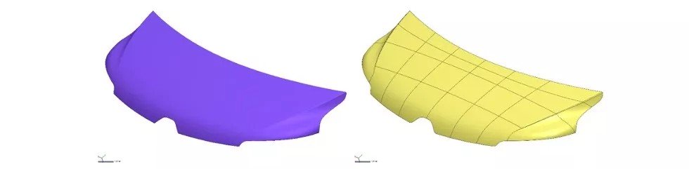
Car mask made in GeoMagic Design X using autosurface
An additional modeling method that can combine the two previously mentioned is adaptive modeling, which involves designing in a real-world environment. It is used, for example, when we want to modernize an existing machine and incorporate new components or equipment into its design.
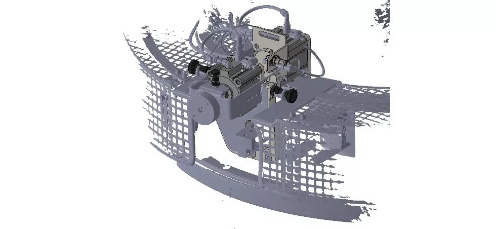
Adaptive modeling of a new actuator using existing mounts
Verification
Every final product needs to be inspected. It is no different with a CAD model generated from a 3D scan. Professional reverse-engineering programs have built-in tools that allow you to check on the fly how far the created model deviates from its physical prototype, thanks to which you can easily assess the quality of the CAD model.
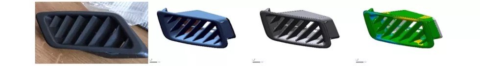
Comparison of the completed CAD model with the 3D scan
Optimization and production
A huge advantage of reverse engineering is the ability to make changes at any stage of modeling. In the case of recreating a worn-out, run-down, obsolete or inefficient object, we can upgrade and improve it on the fly, so that the final product is adapted to modern requirements, but retains unchanged essential information, such as fastening points, dimensions or overall shape. Modeling with the ability to edit all geometries also comes in handy when we have to take into account modern manufacturing methods and Industry 4.0. Thus, reverse engineering is a comprehensive process of constructing a modern product, adapted to modern requirements, based on existing, often old designs.
A suitably upgraded product can be flat-documented and the design forwarded to production.
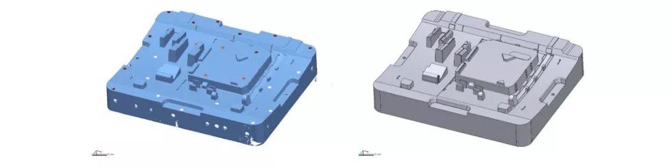
An example of reverse engineering an injection mold
Summary
Reverse engineering provides the ability to recreate reality in digital space. Thanks to modern 3D technologies, we can bring to life or use in a project any physical object for which there is no documentation. A key step in the entire process is 3D scanning, the proper execution of which is essential to achieve the expected results.
Taking 3D measurements with an inaccurate 3D scanner can lead to the failure of the entire process and the production of a product that deviates from the physical base on which we are based. Of course, professional software and an experienced designer are capable of completing the model in under-scanned areas, or repairing run-out data, but they will not be able to improve the accuracy of the model if the 3D data provided is made with inaccurate equipment. Therefore, when embarking on the implementation of reverse engineering, it is important to pay attention to what systems are to be used to perform the entire process.
If you have parts that require reverse engineering or are interested in receiving more information about SCANTECH’s innovative metrology 3D scanners or 3D scanning services, please visit www.invizion.pl and contact info@invizion.pl.
We also offer free trial measurements and live demonstrations.


