


Transformation scenarios in the energy sector highlight wind turbines as one of the leading sources of green energy. Large wind farms with a total capacity of 1 gigawatt (GW) are planned to be established off the Polish Baltic Sea coast. Considering this, we cannot overlook the production aspect and the quantity of wind towers that will be erected in offshore and onshore areas in the near future.
Many companies already have production capabilities, but many are also considering supplementing and modernizing their machinery parks. A recent September survey conducted by the B2B Keralla Research Institute with representatives from 400 small and medium-sized manufacturing companies indicates that nearly half of the companies in the metalworking industry plan to invest in machinery and equipment. Many of them are considering production for the energy sector. Following this trend, we decided to present, in part, the technology of manufacturing components for wind turbines and answer some questions that will shed light on the technologies used in production.
In the last 40 years, the development of wind turbines has led to nearly a twentyfold increase in rotor diameters. The requirements for torque in planetary gearboxes have also changed.
Modern designs of planetary gearboxes, used in wind turbine construction, offer significantly better technical parameters than those designed a decade ago. They provide higher torque and much higher torque density [Nm/kg], while reducing the weight and dimensions of the gearbox. All of this has a significant impact on gear wheels, gearbox housing dimensions, and their production. Presently, planetary gearboxes are designed and manufactured to achieve an increase in torque density, increased vibration resistance, and reduced noise levels.
WHAT SHOULD WE CONSIDER WHEN CHOOSING MACHINES FOR MACHINING GEARBOX HOUSINGS?
Machining gearbox housings requires high precision and accuracy, with a strong emphasis on shape and position tolerances. These criteria in terms of both individual and serial production can only be met by a solid and high-quality machine, which includes features such as a thermosymmetrical design and proper heat source management, including the distribution of heat from coolants, control cabinets, and hydraulic units. The generated heat should also be removed from the machine’s workspace to maintain a uniform temperature distribution. A stable and thermosymmetrical machine structure ensures smooth and precise movements of axes without jerks or jumps, impacting geometry optimization and surface machining precision. Chip removal in the workspace and temperature regulation of the coolant used in the process are also crucial. Electronic compensation, combined with increased geometric accuracy of the machining center, adapted to production conditions, is essential for fully utilizing the machine’s capabilities. To fully utilize a machine’s capabilities, it must be placed on a foundation with adequate rigidity, adapted to local conditions.
WHAT SHOULD WE CONSIDER WHEN CHOOSING MACHINES FOR GEAR MACHINING?
In the case of gear machining machines, the coupling of the table rotation axis with the milling head is of paramount importance. The table drive plays a crucial role and is responsible for high indexing accuracy. Undoubtedly, the best guarantee of indexing accuracy is a worm gear in combination with hydrostatic table bearings and fully automatic hydrostatic load compensation. Moreover, when considering the production of gears, including planetary gears, attention must be paid to external and internal gear cutting.
For the machining of gears with internal gearings, a milling head is necessary, characterized by both sufficient power and a compact design. Gleason milling heads have an adequate power reserve, enabling them to work with the latest cutting tools such as Opti-Cut® cutters with replaceable inserts. When choosing a machine, it is also essential to consider the possibility of both wet and dry milling.
Below are two examples of solutions related to the machining of components for wind turbines. We present machining on pallet machining centers and gear hobbing machines for gears.
EXAMPLE 1
MACHINING GEARBOX HOUSINGS
OBJECTIVE: The task was to develop automated and highly flexible machining for planetary gearbox housings used in wind turbines.
CHALLENGE: The client’s production portfolio includes a variety of products, mostly made of cast iron, including cast iron with spheroidal graphite GGG70 for gearbox housings. The weight of the components reaches 4500 kg. The proposed technology should be an alternative to machining on vertical lathes. Machining of deep surfaces and holes using a retractable spindle is required. The machining time must not exceed 3 hours. Production needs and flexibility in project handling impose additional requirements, such as a large tool magazine capacity and the ability to handle oversized tools. The machine must be characterized by increased positioning accuracy in linear and rotary axes and ensure high availability of the entire machining station in a multi-shift system.
SOLUTION: For the machining of gearbox housings, two STARRAG Heckert HEC 1600 P Athletic pallet machining centers with the following specifications were used:
- Palette size: 1800 x 1600 [mm]; load capacity: 12400 [kg]
- Travel in X/Y/Z axes: 2800/ 2100/2100 [mm]
- Horizontal spindle with retractable NC quill with 750 [mm] stroke
- Spindle drive: 56 [kW] and 4000 [min-1]
- NC rotary table
- Tower tool magazine with 180 positions
- Max. Ø 980 [mm] for bridge tools
- Max. 800 [mm] length
- Max. 50 [kg] weight
- NC angle milling head
- Cooling unit with fabric filter and coolant temperature control, coolant pressure supplied by the spindle: 70 [bar]
- Positioning accuracy P / position scattering width Psmax
- Linear axes: 0.006 [mm] / 0.004 [mm]
- Rotary axes: 6”/4”
- Laser tool probe
- 3D part probe
Technological processes:
- Setting up and preparing the part using a 3D probe
- Single-setup machining
- Comprehensive machining including boring, milling, chamfering, and threading
- Max. tool dimensions
- Bridge tool with a max. Ø650 [mm]
- Boring bar with a length of 735 [mm]
- NC angle milling head for hole machining
BENEFITS: The machines and production technology used provided flexible and comprehensive machining with reduced machine and setup times. Very high accuracy was achieved in both individual and serial production. For example, the surface quality of bearing holes was Ra 1.6 µm. The cycle time is below the client’s requirements and amounts to 164 minutes. High positioning accuracy was also confirmed: planetary gear holes 600 mm apart from the base hole with a deviation of 0.04 mm. The use of a retractable spindle and an NC milling head optimizes the machining center’s production capabilities and provides high flexibility. Monitoring and control devices reduce maintenance and operating costs, resulting in efficient tool and part handling. A fault diagnosis system that minimizes downtime had a positive impact on availability, which, in this case, reached ≥ 95% for multi-shift work. Ultimately, the client also experienced a reduction in operational costs due to the use of energy-efficient machine components.
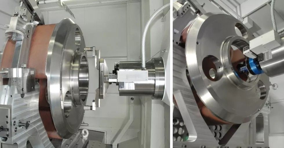
Finishing with a bridge tool Ø650 mm / hole drilling using an angle head Finishing with a bridge tool Ø650 mm / hole drilling using an angle head / Photo: Starrag
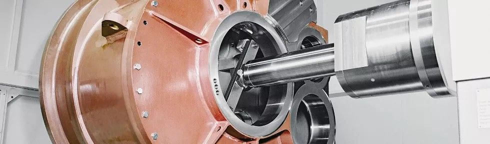
Bridge tool on a retractable spindle / Photo: Starrag
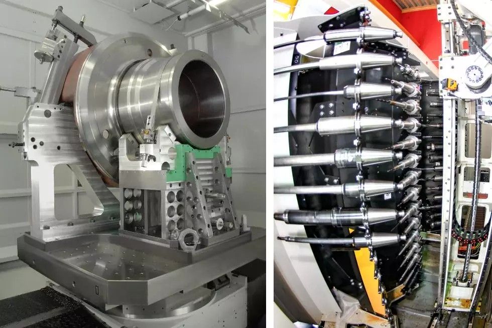
Gearbox housing clamping system / tool magazine, oversized tools / Photo: Starrag
EXAMPLE 2
GEAR HOBBING OF GEAR WHEELS WHAT IS GEAR HOBBING?
During gear hobbing, a cutter and the workpiece move as if they are interlocking with each other. A hob moves across the face of the workpiece, sequentially cutting each tooth profile with its cutting edges. At each change in the cutter’s position, the cutting edge removes a layer of material from the workpiece, as shown in the attached video. This is the most popular method for milling gear wheels.
HOW ARE GEAR WHEELS MANUFACTURED?
In addition to gear hobbing, another method of making gear wheels is shaping, in which the hob imitates the shape of the cutter’s teeth over the entire length of the gear. This method is suitable for rough machining and for gears with lower precision requirements. Another method is broaching, in which a tool in the form of a wheel, called a broach, makes a vertical working movement, and the workpiece is rolled over the tool. Both the workpiece and the tool perform rotational movements along pitch circles. Modern methods of manufacturing gear wheels allow for machining hardened materials. Power Skiving technology is useful for high-efficiency production of external and internal cylindrical gears. It is a technology that enables very high-quality gear teeth and offers significant financial benefits in serial production. Power Skiving also allows for profile and tooth line modifications, opening up new possibilities, especially where other methods are technically restricted. Such applications are successfully used in Poland, particularly in the aerospace and automotive industries. But that’s a topic for another time.
REQUIREMENTS FOR HIGH-QUALITY GEAR MACHINING?
Requirements for gear machining are focused on reliability and correct gear interaction. The goal is to evenly transmit motion, work quietly, and ensure the longevity of the gearbox. Any dimensional or shape deviations can lead to serious consequences, including uneven gear pair interaction. Accelerations or decelerations of the driven elements of the gearbox lead to increased dynamic loads, including vibrations and gearbox damage. Good quality gearing provides proper gear support and the correct engagement of the gear teeth. Contact stresses are crucial for gearbox durability. The transmitted torque and the gear contact area influence tooth meshing forces. Gear topics are highly complex.
OBJECTIVE: Increase torque density, improve vibration resistance, reduce noise levels.
SOLUTION 1: Gear Hobbing / Gleason P1200 Gear Hobbing Machine / gear Number of teeth: 47 Module: 12 Pressure angle: 20 degrees Helix angle: 9 RH Outer diameter: 600 [mm] Face width: 260 [mm] Material: 17CrNiMo6 (1150 N/mm2)
Technological data: Gleason P1200/P1600 gear hobbing machine Rough milling before grinding, 2 passes, wet machining Hob type: EZ, G30, TiAIN-coated Hob made in class B Cutting speed: 40/60 [m/min] Axial feed: 2.8 / 5.8 [mm] Chip thickness: 0.22 [mm] Machining time: 114 [min]
BENEFITS OF MACHINE SELECTION: EZ cutters provide fast chip removal. Approximately two-thirds of the cut is performed by the upper part of the cutter teeth. EZ cutters have specialized grooves that provide more cutting edges at the ends of the cutter teeth, allowing for higher feeds up to 185%! This reduces machine load, the number of passes, shortens cycle time, and increases tool durability.
SOLUTION 2: Gear Hobbing / Gleason P2400 Gear Hobbing Machine / ring Number of teeth: 99 Module: 18 Pressure angle: 20 degrees Helix angle: 7 LH Outer diameter: 2100 [mm] Inner diameter: 1780 [mm] Face width: 480 [mm] Material: 17CrNiMo6 (1150 N/mm2)
Technological data: Gleason P2400 gear hobbing machine with internal head IFK2 Rough milling before grinding, 2 passes, wet machining Opti-Cut hob for rough machining with carbide inserts and TiAIN coating Effective number of teeth: 10 / 5 Cutting speed: 130/150 [m/min] Axial feed: 3.7 [mm] Chip thickness: 0.11 [mm] Machining time: 330 [min]
BENEFITS OF MACHINE SELECTION: Opti-Cut hob cutters are designed for single or multiple passes depending on the process and machine. For rough and finish machining, they provide higher cutting speeds than HSS cutters.


