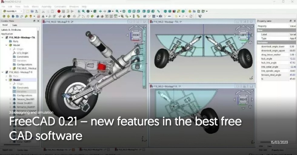
CAD software forms the foundation of modern design processes in every field of engineering. Tools of this kind usually offer much more than just 3D modeling – they allow for generation of toolpaths for CNC machines, analyses of kinematics of assemblies or simple numerical simulations. Currently, there are many solutions of this kind available on the market. However, there is an increasing issue with their accessibility. Licensing becomes subscription-based, total costs increase and free versions meant for limited applications are discontinued.
This, combined with the fact that an increasing number of small companies, freelancers, hobbyists, and students seek cost-free or low-cost solutions, provides a field for development of independent software with favorable licensing. Unfortunately, when searching for completely free 3D CAD environment for all applications, we come across only one noteworthy solution – FreeCAD. It is an open-source software, which has remained largely unnoticed since its initial release in 2002. To this day, many people consider this environment unintuitive, difficult to master and unsuitable for everyday work. What is the reality? In this article, prepared on the occasion of the release of the new version of FreeCAD 0.20 (which took place on June 14, 2022), I will attempt to answer this question.
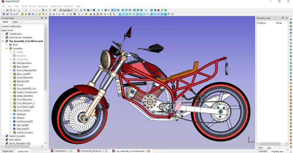
Source: https://forum.freecadweb.org/viewtopic.php?f=24&t=67784
What can be done in FreeCAD and what are its weaknesses?
Of course, FreeCAD, like any other software (especially open-source), is not flawless. However, its rapid development and significant contributions of a growing community make it noteworthy and suitable for a wide range of applications. Following the discussions on FreeCAD’s forum, it’s easy to notice that this software is often used for the preparation of models for now widespread 3D printing. However, this is not its only application. FreeCAD is also well-suited for commercial purposes and scientific projects. While it is impossible to list all the interesting applications of FreeCAD discussed on the forum, it is worth mentioning tools developed by one of the largest scientific laboratories in the world – Oak Ridge National Laboratory, where the first continuously operated nuclear reactor, crucial in atomic bomb development, was created. This software, named HEAT, is also open-source and can be used for thermal calculations of tokamak reactor components. HEAT utilizes FreeCAD for geometry preparation.
When it comes to more standard applications, FreeCAD currently includes several built-in modules not only for 3D modeling but also for finite element analysis (FEA) and machine toolpath generation. These modules will be further discussed in the later part of the article. While delving into more specific description of FreeCAD, it is important to remember that this software is still under active development and does not yet include all functionalities offered by commercial equivalents. However, workarounds exist for practically all limitations. They were recently documented in the FreeCAD’s wiki documentation in the Workarounds section. The limitations mainly apply to certain sketcher functions (such as lack of tools for circular patterns, chamfers and offsets) and, to a lesser extent, to 3D modeling operations (for example, no dedicated tools for the creation of ribs and cosmetic threads). There have already been efforts to significantly enhance the sketcher and all the aforementioned tools (plus many others) should be added in the future. Until then, the aforementioned workarounds suffice.
Another issue with FreeCAD is that some of the existing tools don’t always function correctly and have somewhat limited capabilities. This particularly applies to fillets and chamfers, which in certain cases cannot be created and cannot absorb adjacent surfaces. Frequent issues also arise with the thickness (hollowing) tool. Moreover, 2D and 3D offsets don’t always function as intended. However, these imperfections are not a fault of FreeCAD itself – they result from bugs in the OpenCASCADE (OCC) engine, on which FreeCAD relies. OCC is the only open-source CAD engine, and one can only hope that its creators will eventually resolve long-known problems mentioned in this paragraph.
The last and arguably the most significant issue (though its importance depends on the way the software is used) is the so-called TNP – topological naming problem. In essence, it refers to models breaking when significant changes are made, if features like sketches are based on existing geometry (e.g. sketches created on model’s faces). This results in references being lost due to changes in the internal naming of geometric entities. However, this issue has been nearly entirely resolved by a user named Realthunder, who created a modified version of FreeCAD known as Link Branch, which is also free and open-source.
Furthermore, there are plans to integrate the code fixing the TNP into the original FreeCAD version, effectively eliminating this issue. This is expected to take place in the upcoming version, which due to the resolution of such a crucial problem, will be designated as version 1.0. Until that happens, caution is advised when modeling using references to existing geometry – it is recommended to base sketches on the properly positioned datum planes instead of model’s faces, for instance. Alternatively, one can use the forked version of FreeCAD developed by Realthunder. This can be a good solution since this version improves much more than just the infamous TNP.
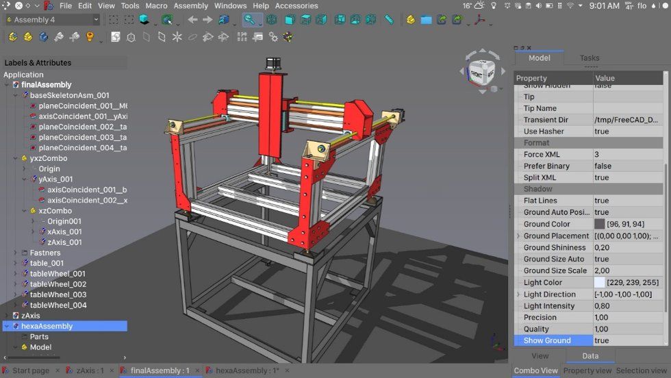
It features a more modern, customizable interface, allows the creation of multiple bodies within a single Body object (which is not possible in the official version – separate Bodies need to be created for individual solids or one needs to use operations like mirrors or linear patterns in a different module, as will be discussed later), facilitates geometry projection in sketches and enables more advanced rendering, among the others. The Link Branch version is showcased with interesting examples on the OficineRobotica YouTube channel, from which the screenshot below was taken.
Source: https://forum.freecadweb.org/viewtopic.php?f=24&t=5750&p=399417#p399417
Workbenches in FreeCAD
As mentioned earlier, FreeCAD is a modular software. Some modules (workbenches) are built-in, while others, less commonly used and developed by various users, need to be downloaded and installed separately. This can be done using the built-in tool, which also manages updates for modules downloaded from GitHub and is used to download macros helpful when certain tools are missing or certain modeling stages can be sped up.
Many users without experience with FreeCAD highlight the fact that its non-intuitiveness largely stems from the fact that upon launching the software, it’s not immediately clear which module to use. However, this can be explained easily – for 3D modeling, one should use the Part Design module, without the need to separately enter the Sketcher workbench. These two modules are switched automatically when creating and exiting a sketch. For certain types of 3D operations, such as offsets, creation of surfaces from sketches, or Boolean operations, the Part module has to be used. Some of its tools overlap with Part Design, but have distinct names due to different principles. The Part workbench employs the traditional CAD modeling technique known as CSG (Constructive Solid Geometry), based on geometric primitives and Boolean operations.
While it is usually recommended to avoid mixing Part Design and Part workbenches, in more complex cases, it might be necessary to utilize tools available in the Part workbench when their PartDesign counterparts fail or when surface modeling is concerned. Another important module is Draft. In theory, it is meant primarily for 2D geometry creation but it also supports 3D objects. The capability to switch between sketches from the Sketcher workbench and Draft objects aids in filling certain gaps in the Sketcher, allowing for 3D sketches or offsets. Additionally, the Draft module offers tools for advanced patterns, enabling the creation of object copies beyond a single Body, as well as scaling and geometry translation/rotation, along with interesting Upgrade and Downgrade options that transform the geometry to higher or lower level (e.g. from a solid to individual faces then to edges and vice versa), respectively.
Apart from the aforementioned modules, FreeCAD includes several other noteworthy built-in workbenches. Among them is TechDraw, used to create 2D documentation based on 3D models. This module is evolving rapidly and is already close to its commercial CAD counterparts in terms of functionality. Another interesting workbench is FEM, supporting finite element analysis (FEA). It utilizes several free solvers but mainly relies on CalculiX. It is far from the convenience and capabilities of PrePoMax, described in other articles but it is suitable for relatively simple analyses. It also supports beam elements, currently unavailable in PrePoMax. Another important built-in workbench is Path, used to design toolpaths for CNC machining, currently limited to 3-axis operations. Other modules worth mentioning are Arch (BIM – Building Information Modeling), Mesh Design (tools for working with surface meshes), Surface (a set of tools for basic operations on NURBS surfaces) and Spreadsheet (creating spreadsheets for model parameterization).
A significant advantage of FreeCAD is the availability of many additional modules. According to the author, some of the most interesting ones are:
- A2plus – assemblies – FreeCAD currently lacks an official module for this but apart from A2plus, there is also Assembly3 and Assembly4. A2plus can be considered the most intuitive and closest to what is available in commercial software but the other two allow for more advanced workflows.
- Curves – modeling curves and surfaces
- Curved Shapes – surfaces spanned on curves
- Dodo – structural profiles
- Sheetmetal – sheet metal part design
- Fasteners – library of fasteners
- Exploded Assembly – exploded views
- freecad.gears – gear generator
- Manipulator – manipulation of objects in 3D space (a simplified approach to assemblies)
- Lattice2 – complex arrays and lattice structures
- CfdOF – Computational Fluid Dynamics (CFD) analysis using the OpenFOAM solver – not essential for all users, but it is the only free graphical environment for this solver and works very well, still gaining new capabilities.
There are also other add-on modules that are not yet available through the add-on manager and require manual installation. These include the Dynamics module, allowing for kinematic analyses using the open-source MBDyn solver. There are also fairly specific workbenches for tasks such as ship, turbine or even guitar design.
Learning how to use FreeCAD
FreeCAD keeps gaining popularity and there is an increasing amount of resources available to make it easier to start working in this software. FreeCAD is quite specific and some habits from commercial solutions can make it more difficult to master this open-source environment. However, it is worthwhile to give this software a chance and not be discouraged by encountered challenges. On YouTube, there are numerous helpful tutorial videos, including those on the MangoJelly channel, by many considered as the best FreeCAD tutorials.
A key source of information about the software is its documentation, which in this case consists of articles on the wiki. If difficulties are encountered, it is recommended to reach out for help on the FreeCAD forum, where an active community can be found. Answers to questions are usually obtained very quickly there. The forum is also used bug reports, feature requests and discussions about various aspects of the FreeCAD’s development.
Summary
FreeCAD is a software that requires a certain amount of patience and a willingness to let go of some habits from commercial environments. At the same time, it can help one develop creativity and 3D modeling skills. FreeCAD has impressive capabilities for a fully free software and its range of applications is not significantly different from the commercial counterparts. Contrary to appearances, it is feasible to create large assemblies within it. Of course, there might be performance issues with complex models but such difficulties are also encountered in commercial software, which can also prove unstable.
Limitations of the available features are typically addressed and rarely pose a significant problem, as workarounds are almost always available. A significant advantage of FreeCAD for many users lies in its broad capabilities related to macros and Python scripting. This enables the automation of many tedious modeling workflows. Another helpful feature is support for 3D manipulators.
When using FreeCAD, it is also worth contributing to its development in any way. Even by just reporting bugs on the forum, but if one has some free time, it is possible to support the FreeCAD’s community to a greater degree in various ways. People who can write the code to implementing even small new functionalities are always welcome. This sometimes comes down to copying and modifying the existing code, but someone needs to do it and the core developers are often engaged in more substantial efforts to improve the software.
It is worth mentioning the availability of different versions of FreeCAD. The so-called development version is always available and includes recent changes (features and bug fixes) while being portable (no need for installation). It is regularly updated based on the source code on GitHub and can be found on the weekly builds page. On the other hand, the stable version is typically released once a year, usually in the first half of the year. It can be downloaded from the FreeCAD’s homepage (Downloads tab). It requires installation and, like the development version, is available for Windows, Linux, and Mac systems. In principle, using the development version is recommended, which although theoretically not as stable as the stable version, corrects many errors and introduces new functionalities. The list of changes in successive releases of FreeCAD is continuously updated and available for version 0.20 at this address: Release Notes.
In conclusion, I encourage readers to download and test the newly released version 0.20 of FreeCAD. With the right approach, it can become an incredibly useful tool not only for hobbyists but also for engineers using CAD software more or less commonly for professional purposes.


