Each CNC machine control has a database of more or less developed machining cycles. They are an important component of the programs that control the operation of the machine.
As a rule, these are fixed, parameterised subprograms stored directly in the control system. We can often define them using an easily interpretable module for dialogue programming, which graphically displays the meaning of the individual parameters. This makes it much easier to define the correct values for a specific situation. The machining cycles not only make the programmer’s life easier, but also allow better use of the machine’s potential.
The main benefits of using cycles are:
- program transparency
- significant reduction of the number of blocks
- reduced programme development time in the case of machine programming
- makes later editing and optimisation of the programme easier
- allows more productive machining strategies to be used
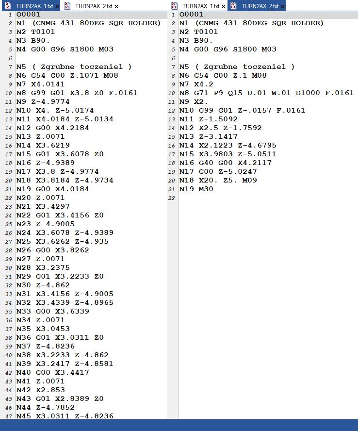
Figure 1 Comparison of the standard programme (left) and using the G71 cycle (right)
The cycles can vary greatly depending on the version of the control or machine manufacturer. This can cause significant problems with the interpretation of such code for people who are not familiar with the control. FANUC, SINUMERIK or HEIDENHAIN have completely different approaches to the definition of cycles. They differ not only in the code that calls them but also in the parameters that we can define when triggering it.
Drilling cycles
Drilling cycles include operations for machining holes using various tools, e.g. drills, countersinks, reamers, taps. Apart from being able to use these cycles by creating a program at the machine’s desktop, in most cases CAM programs can also generate point operation codes as machine-specific cycles.
Below are examples of threading cycles in different controls.
On the Sinumerik 810D/840D, machining cycles are defined as procedures whose parameters are given together with the cycle name.
CYCLE84(RTP, RFP, SDIS, DP, DPR, DTB, SDAC, MPIT, PIT, POSS, SST, SST1,
_AXN)
RTP – Withdrawal plane (absolute)
RFP – Reference plane (absolutely)
SDIS – Safety clearance (incremental, no sign)
DP* – Final threading depth (absolute)
DPR* – Final threading depth (incremental, no sign)
DTB* – Waiting time at final depth (chipbreaking)
SDAC – Direction of rotation at the end of the cycle : 3, 4 or 5
MPIT* – Thread pitch as thread size with sign.
Range of values: 3 (for M3) … 48 (for M48)
Mark indicates thread direction (“+” right, “-” left)
PIT* – Thread pitch as a value (with sign)
Value range: 0,001 … 2000,000 mm
Sign determines thread pitch direction (“+” right, “-” left)
POSS – Spindle position for oriented stop (in degrees)
SST – Speed for threading
SST1 – Speed for reversing
_AXN* – Tool axis: 1, 2 or 3 (defined by G17/G18/G19)
Where CYCLE84 is the name of the cycle. In this case it is threading without the use of a compensating chuck, while in brackets are specified the further values of the parameters of this cycle. These can be specified as constants or as variables (R-parameters). When programming at the machine’s desktop the graphic control module will tell us what the successive parameters mean, thanks to which we can easily define the whole cycle.
In addition, the invocation of machining cycles can be non-modal, in which case they refer to only one block, or modal, i.e. in each block with a tool movement to refer to. To invoke such a cycle modally, enter MCALL in the given block, so that in the following lines with tool movement instructions, the modal cycle is automatically invoked after the execution of these movements.
Modal cycle is cancelled when the MCALL address is programmed without a cycle call.
N10 MCALL CYCLE100(34,67,2) ; modal cycle call
N15 G0 X20 Y30 ; first execution of the cycle
N20 Y50 ; second execution of the cycle
N25 Y100 ; third execution of the cycle
N30 MCALL ; cancellation of modal cycle
In the Heidenhain 530/640, by contrast, the definition of a similar cycle follows:
CYCL DEF 207 THREADING GS NEW
Q200=2 ;SAFE HEIGHT – safety clearance
Q201=-20 ;SPEED – thread depth
Q239=1 ;TAPPING PITCH – Mark defines the direction of the thread turn (“+” right, “- ” left)
Q203=-10 ;SURFACE COORDINATES – Coordinates of the object surface
Q204=20 ;2. safety clearance
Each parameter is defined on a separate line, while the comment always contains a description of the parameter. The programmer writing the program on the machine can also use the graphical hint. As with the Simumerik, it is the Heidenhain control that calculates the appropriate feed rate for a particular thread based on predefined rotations. In the cycle itself we are also able to define whether this is to be a left or right thread. All cycles in Heidenhain work after an appropriate command has been called.
It can be:
CYCL CALL: works in rows
CYCL CALL PAT: operates in rows in combination with point tables
The operation for subsequent points is called after the M99 block has been written to. For each row in which this cycle is to be called, this command must be added. In contrast, M98 works modally, depending on the parameters of the machine itself.
The threading cycle in the Haas control looks like this:
G84 F J L R X Y Z S ;
F – Feed rate
J – Multiple withdrawal (example: J2 will retract at twice the
cutting speed)
L – Number of holes when using G91 (incremental mode)
R – Position of the R plane (over the workpiece)
X – Location of the hole on the X axis
Y – Location of the hole on the Y axis
Z – Z axis position at the bottom of the hole
S – Optional spindle speed
Compared to SINUMERIK and HEIDENHAIN controls, the Haas cycle is much simpler. The main difference is that we have to calculate the appropriate feed rate ourselves. What is more, this cycle is only used for right-hand threads. If we wanted to make a left-hand thread, we would have to use a completely different code, in this case it would be G74.
Milling cycles
Milling cycles are a set of control-specific subroutines for machining flat surfaces, grooves, pockets, etc. performed on milling machines. The variety of shapes, the multitude of parameters to be set and the limited strategies mean that they are only used in practice with manual programming.
With modern CAM software, we are able to create a programme for machining a specific shape much faster. What is more, on the machine we have very limited possibilities to influence the shape of the path. In CAM programs we usually have a wide range of much more efficient strategies than what is available on the machine.
The most commonly used milling cycle is the rectangular pocket milling cycle.
In SINUMERIC it looks as follows.
POCKET1(RTP, RFP, SDIS, DP, DPR, LENG, WID, CRAD, CPA, CPD, STA1, FFD, FFP1, MID, CDIR, FAL, VARI, MIDF, FFP2, SSF)
RTP – Withdrawal plane (absolutely)
RFP – Reference plane (absolute)
SDIS – Safety distance (incremental, no sign)
DP* – Ultimate pocket depth (absolute)
DPR* – Final pocket depth (incremental, no sign)
LENG – Pocket length (without or with sign)
WID – Width of the pocket (without or with sign)
CRAD – Corner radius (without sign)
CPA – Midpoint abscissa (absolutely)
CPO – Centre point abscissa (absolutely)
STA1 – Angle between the longitudinal axis and the abscissa: 0° ≤ STA1 < 180°
FFD – Feed rate for infeed
FFP1 – Feed rate for side machining
MID – Maximum infeed depth (no sign)
CDIR – Direction of machining: 2 (G2), 3 (G3)
FAL – Finishing allowance for side machining
VARI – Machining type:
0 – complete machining (roughing and finishing)
1 – roughing with allowance
2 – Finishing only
MIDF – Maximum infeed depth for finishing
FFP2 – Feed rate for finishing
SSF – Speed for finishing
The cycle definition for the same geometry in HEIDENHAIN would be as follows:
12 CYCL DEF 4.0 POCKET MILLING
13 CYCL DEF 4.1 ODSTEP 2 – Safety clearance
14 CYCL DEF 4.2 SOIL -10 – Pocket depth
15 CYCL DEF 4.3 INPUT 4 F80 – Infeed depth and feed rate during recessing
16 CYCL DEF 4.4 X80 – Pocket length
17 CYCL DEF 4.5 Y40 – Pocket width
18 CYCL DEF 4.6 F100 DR+ PROMLINE 10 – Feed rate, direction of movement:
concurrent milling at M3: DR+
counter milling at M3: DR-
Rounding radius: radius for pocket corners
19 L Z+100 R0 FMAX M6
20 L X+60 Y+35 FMAX M3
21 L Z+2 FMAX M99
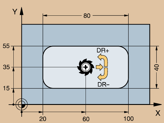
Figure 2. Declaration of the direction of motion in the Heidenhain control
In contrast, in the HAAS control, the pocket machining is defined by the code
G150 D F I J K P Q R S X Y Z
D – Tool radius/diameter correction selection
F – Feed rate
I – Incremental cuts of the X axis (positive value)
J – Incremental cutting of Y axis (positive value)
K – Finishing pass value (positive value)
P – Number of the subroutine that defines the pocket geometry
Q – Incremental depth of cut in the Z axis per transition (positive value)
R – Position of the R plane of the rapid motion
S – Optional spindle speed
X – Start position X
Y – Start position Y
Z – Final depth of the pocket
The main difference between these controls is that in Haas, even for a simple pocket, we will have to create a P## subroutine that defines the geometry of the pocket of the enclosed area using G01, G02 and G03 movements in the X and Y axes. The G150 command results in a search for an internal subroutine with the number N, specified by the P code.
Compared to HAAS, the definition of SINUMERIK and HEIDENHAIN cycles is more descriptive. From the desktop of the machine we will have graphical hints as to what a given parameter means. Depending on the geometry we want to machine, we have many different cycles available, unlike in HAAS. The parameters used in these controls differ from each other by designation, while their functions are similar.
The most important thing in the process of defining milling cycles on the machine will in any case be the time of its definition and the possibility of applying various strategies. In this respect, almost any CAM software will be better than programming on the machine. Not to mention defining cycles for more complex shapes.
Turning cycles
The situation is slightly different with turning cycles, which in most control systems include the most common operations: turning, boring, groove turning, thread turning or undercutting. Additionally, there are cycles for machining holes, which are often derived from the drilling cycles described above. In turning, we are dealing with much simpler geometries, which is why the manual programming is still very popular. The principle is still the same. We have a few parameters to define and a profile to describe. It is worth mentioning that some CAM programs are able to generate the code as a proper machine cycle, so the program becomes clearer and shorter.
One of the more complex turning cycles on the Sinumerik is CYCLE95. Its task is roughing and/or finishing of external or internal surfaces. With it we are able to program even complex shapes defined by an appropriate contour in the form of a subprogram.
CYCLE95(NPP, MID, FALZ, FALX, FAL, FF1, FF2, FF3, VARI, DT, DAM)
NPP – Name of the contour definition subprogram
MID – Infeed depth (no sign)
FALZ* – Finishing allowance in longitudinal axis
FALX* – Finishing allowance in transverse axis
FAL* – Finishing allowance
FF1 – Feed for roughing without undercutting
FF2 – Feed for roughing undercut
FF3 – Feed for finishing
VARI – Type of machining, range of values 1¸12
DT – Stop time for chip breaking
DAM – Cutting distance for chip breaking
Machining is carried out using a series of parallel passes (radial or axial). It is important to select the VARI parameter, which defines the type of machining: external, internal, coaxial, radial, roughing or finishing. In total, 12 different strategies are available. It is very important to define a suitable subprogram containing the machined contour. This is defined using standard G-codes (G1, G2, G3).
At FANUC we have several cycles for turning, with consideration of the shape of the finished part.
The G71 cycle is an example of rough turning with longitudinal feed.
G71 U R
G71 P Q V W F S T
N
…
N
U – Depth of cut
R – Rate of pullback
P – Number of the first program block
Q – Number of last program block
U – Allowance amount for finishing in X direction
W – Allowance for finishing in Z direction
F – Feed
S – Spindle speed to be used in the entire block G71
T – Tool and correction for use in entire block G71
As we have already seen many times in the FANUC control, we have a higher number of cycles, whereas compared to SINUMERIK, the individual cycles are much simpler. The same is the case with turning. We have cycles for roughing, finishing, copying and many others.
When machine cycles are not enough
It also happens that the control that we have on the machine limits us by only being able to use the cycles that are currently available. In most cases, for standard machining, we only need what the control offers itself.
However, if we have some non-standard operation, or what we have available on the machine is insufficient, we can create our own cycle. I am referring here to the the use of a macro. They increase the possibilities and flexibility of the control system beyond what is available with standard G-code. Potential applications include: families of parts, individualised standard cycles, complex movements and control of optional equipment. This gives us unlimited possibilities.
A macro is an external program, or sub-program, that can be executed repeatedly. A macro instruction may assign a value to a variable or read a value from a variable, evaluate an expression, move conditionally or unconditionally to another point in the program, or conditionally repeat a specific part of the program. Such a program can then be called elsewhere using a special code such as G65 Pxx (FANUC), where Pxx will be the reference to our macro. As in other cycles, it is possible to define the relevant parameters, e.g. depth, feed rate, etc. The control allows variables to be passed between programs, so the macro can read these parameters.
In essence, cycles are there to make much more complex g-code in a simple way. Some cycles allow us to program the machine for machining that would not even be possible with CAM type software. For more advanced technologist-programmers there is the possibility of defining their own macros. However, here the knowledge of the control itself as well as the knowledge of programming in a certain language is essential. There are also companies on the market that can adapt something like this for you.
Such a solution is each time very individualised for a particular machine, control or task, but the possibilities are unlimited.





![By 2030, the market size of metal processing tools is expected to reach $120.44 billion [REPORT] By 2030, the market size of metal processing tools is expected to reach $120.44 billion [REPORT]](https://industryinsider.eu/wp-content/uploads/xcutting-tools-320x167.jpg.pagespeed.ic.SgnEk-RWA-.jpg)