


Currently, the additive manufacturing technique, which is 3D printing, is undergoing a very dynamic development, an example of which are industries considered conservative: automotive and aviation. Despite prejudices, fears and difficulties, additive manufacturing techniques are being implemented more and more often. In the aviation industry, the use of spatially printed parts, which are to replace components made with traditional (subtractive) techniques, must – in accordance with the requirements – undergo certification tests. The cost of this type of research may block the implementation of production.
When it comes to load-bearing structures and structural components, 3D printing of metals is a real applicability of incremental methods (while 3D printing of plastics is only an important area of applicability). Currently, several main methods of 3D printing metals are used. Most of them are based on the use of a building material powder (2.5-axis printing).
CAD / CAM programs and systems in the 3D printing process play a very important role due to the shortening of the technological course of production preparation. The 3D surface model is the basis for developing a CAD design for 3D printing. After the model is synthesized, it is saved in a format with the necessary item data and sent for printing. There is no need to use a post-processor, as in the case of developing a machining program for CNC machining centers.
Optimization of technological processes with the overriding cost criterion requires that – as far as possible – they are minimized. Depending on the design of the printed object, it is often necessary to use supports (Figure 1).
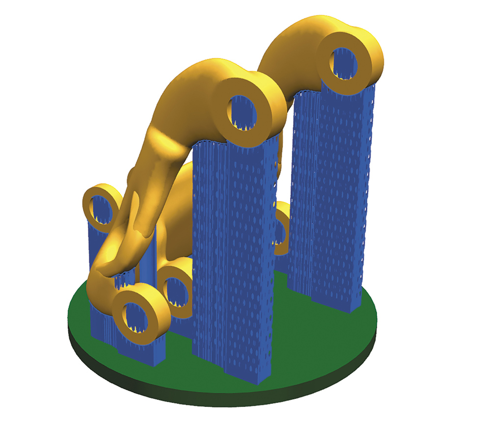
Figure 1. Example of designing supports in 3D print (NX CAD / CAM)
In many cases of 3D printing of powdered metals, it is necessary to use supports. Their design is not a simple activity. The use of supports can reduce costs by printing multiple items in the workspace. In 3D printing from non-metallic materials (plastics), the use of nesting (the distribution of objects produced in the working space of a given printer) allows virtually any mutual arrangement of many items (3D nesting) and thus increases the efficiency of the manufacturing process. On the other hand, in the case of 3D printing from metals, the so-called pattern – 2D nesting (Figure 2).
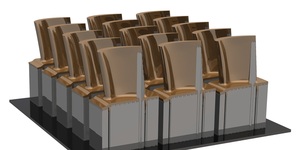
Figure 2. An example of the layout of 3D printed objects from metal – 2D nesting (NX CAD / CAM)
Items manufactured as part of nesting in CAD / CAM programs and systems should be efficiently positioned and arranged in arrays. The layout of the parts sometimes makes it possible to reduce the necessary use of supports, thereby reducing the amount of further finishing that is required.
The condition of the surface layer of printed objects requires further finishing by subtractive methods (machining, abrasive machining). Due to the specificity of possible shapes of printed objects, 5-axis milling is often used (fig. 3). Then, a very good solution would be the ability to freely work on surface and solid models along with preparation of machining, e.g. on a 5-axis CNC milling center (including geometric recognition, machining cycles, machining strategies, tool path synthesis). An example of such a CAD / CAM system is, among others NX 11 by Siemens (Figure 3).
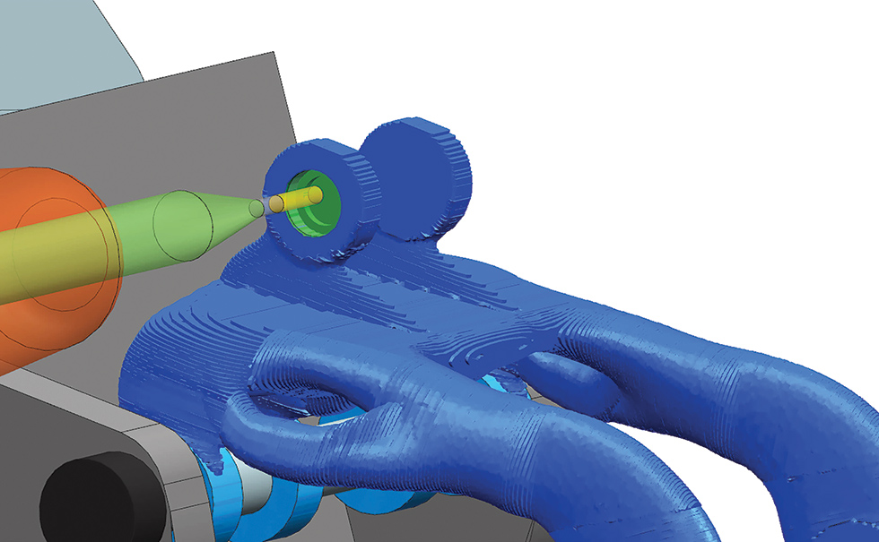
Figure 3. An example of a simulation of the finishing of an object printed with additive technique
In the case of the implementation of 3D printing of some parts, the concept of constructive technology takes on an innovative meaning. Often, the use of incremental manufacturing techniques enables a significant modification of the existing structure – reducing weight, extending the shelf life, improving the desired performance properties (Figure 4). The use of traditional machining methods is not able to ensure the implementation of such modifications.
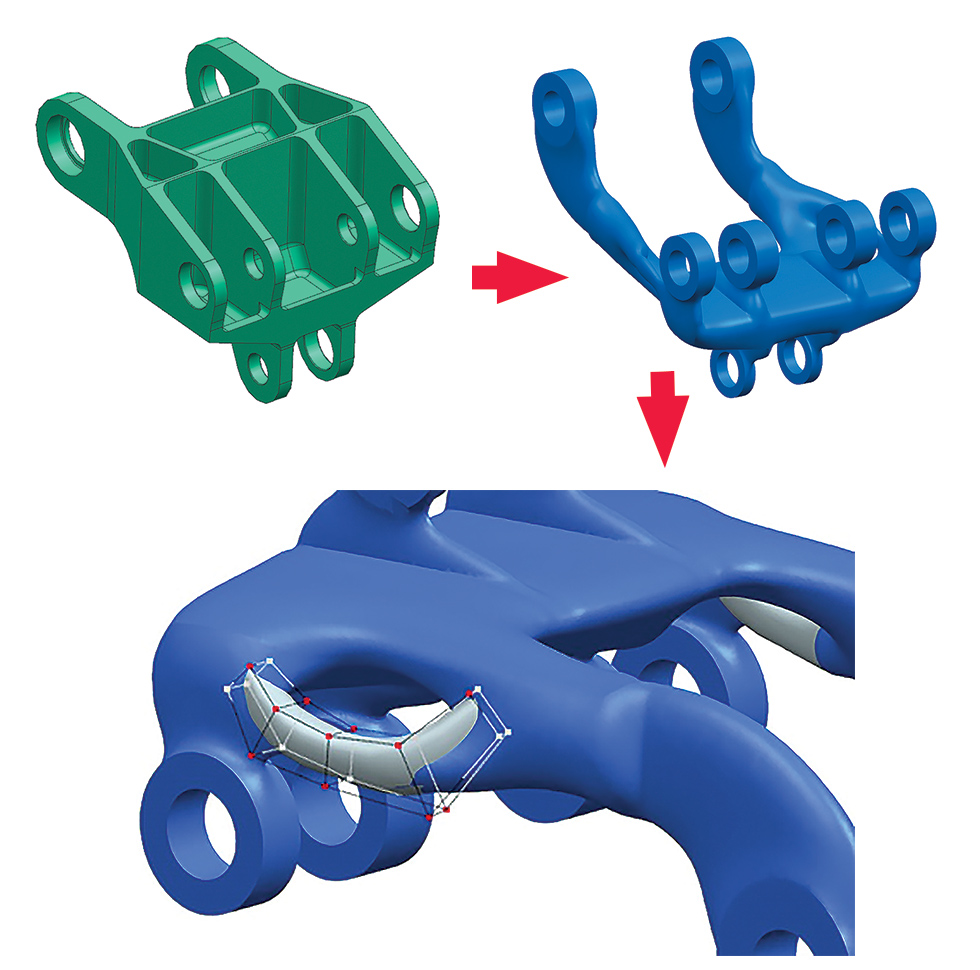
Figure 4. An example of a modification as part of the analysis of the technological efficiency of an object for 3D printing – NX CAD / CAM
In the case of the NX system, Convergent ModelingTM and synchronous technologies were used, which allow you to work on the surface model (derived from the scanning of the object) and the solid model from earlier development works. The synthesis of the object model for 3D printing using automated options and modules makes it necessary to verify the model developed in this way. This verification is an important step in the design process.
CAD / CAM systems should offer verification tools that enable:
- checking the minimum wall thickness;
- analysis of the overhang angle to determine the use of supports;
- recognition of closed spaces, which usually cannot be reached, which prevents their potential processing;
- checking the volume of the printed object in the context of the available printer working space.
Integrated modules (programs) enabling simulations to check whether the resulting projects meet the defined required operational criteria, constitute an additional possibility of verification. Modifying the structure as part of the analysis of its technological efficiency requires the use of tools such as Simcenter 3D (NX CAE), which can function as a completely independent system or integrated with the NX environment or other CAD / CAM system. Figure 5 shows an example of the effects of part topology analysis.
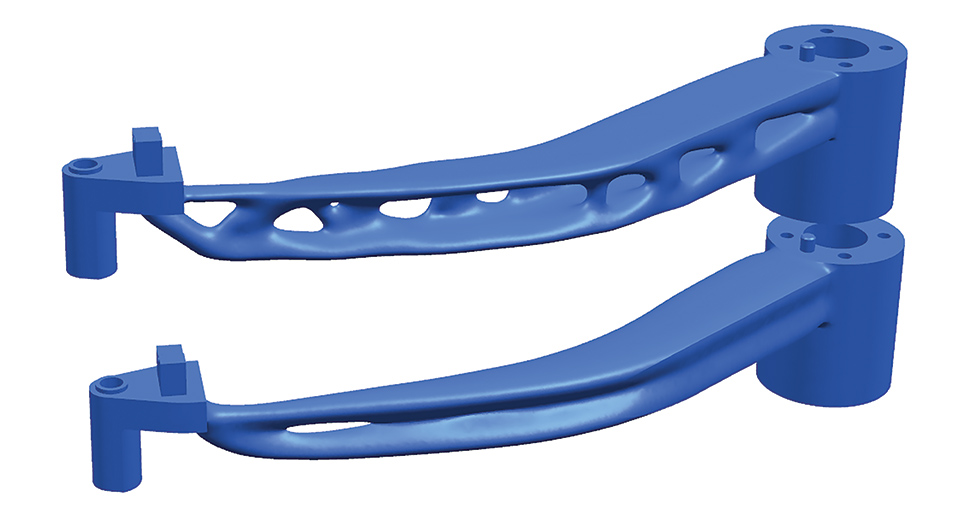
Figure 5. Topology analysis example – NX CAD / CAM
CAD / CAM systems should provide support for machining and hybrid machine tools. Standard methods of 3D printing metals, including SLM, consist in applying a layer of powder and bonding (using a laser beam). The laser surfacing solution with the use of a building material in the form of wire or powder is also used. Hybrid machine tools (specialized design variants of CNC milling machining centers) are used, which, after the 3D printing stage is completed, enable its processing while maintaining the fixing and mounting of the workpiece, which is important for machining accuracy. Examples of such machine tools are hybrid designs from companies such as DMG Mori or the modified Mazak Integrex CNC milling and turning center. In the conditions of research and development centers, there are structures based on standardly available CNC machining centers, which have been modified in-house for 3D printing. In this situation, the implementation of comprehensive support for various manufacturing techniques, including 3D printing as part of CAD / CAM systems, such as NX by Siemens, is a natural way of their development.Źródła


