


Along with the growing popularity of additive technologies, the development of CAD / CAM / CAE programs supporting the process of preparing parts and printing is observed. Due to the fact that it consists of many stages, it is important that the software allows for quick work and the ability to edit the previous steps.
NX’s solution is to close all operations in one system, which eliminates the need to exchange data between different programs. It significantly improves the work, and in combination with the wide range of available tools, the user receives a product that is unique on the market of engineering software.
The process of preparing a 3D printout can start with modeling the geometry using the full design capabilities of NX, loading the resulting model or generating an object using topological optimization tools. Regardless of the stage from which the work was started, the user has at his disposal an extensive tool that allows you to create and edit geometry. In addition to working on the most common wall geometry (B-Rep) among CAD programs, NX allows you to make changes directly to the faceted geometry (e.g. imported from a file in STL, 3MF or point clouds), which is used in incremental technologies.
Before starting the print configuration, check the details in terms of technological limitations of 3D printing. The Design for Additive Manufacturing toolkit enables value control, incl. the overhang angle, the minimum wall thickness, or the minimum radius of curvature of the walls.
The program can also check the solid for the presence of closed internal spaces in which unsintered powder would accumulate, as well as the shape of the channels, e.g. conformal cooling in the molding inserts. The obtained results often require introducing changes in the model, but are not necessarily limited to adjusting the model to the requirements of additive technologies. The use of 3D printing means that geometry can consist of elements not available in other technologies. One of them is the lattice filling structures.
Lattice structures are made of bars connected to form a spatial frame that fills the volume of the element. They have a significant impact on the mechanical and thermal properties of the manufactured parts, as well as on the energy absorption capacity. The effect of their use can be a reduction in weight while maintaining or improving the properties of the detail, and thanks to the smaller amount of necessary material, also reduction of production costs.
The command dedicated to the creation of lattice structures allows for their various creation – volume filling, surface application, as well as the use of an extensive database of ready-made unit cells and those created by the user. Moreover, in order to analyze the final properties of the part, the geometry from the CAD model can be used in the Simcenter 3D calculation module. Data on the lattice structure are automatically converted into 1D elements, which significantly reduces the time needed to prepare the simulation and perform calculations.
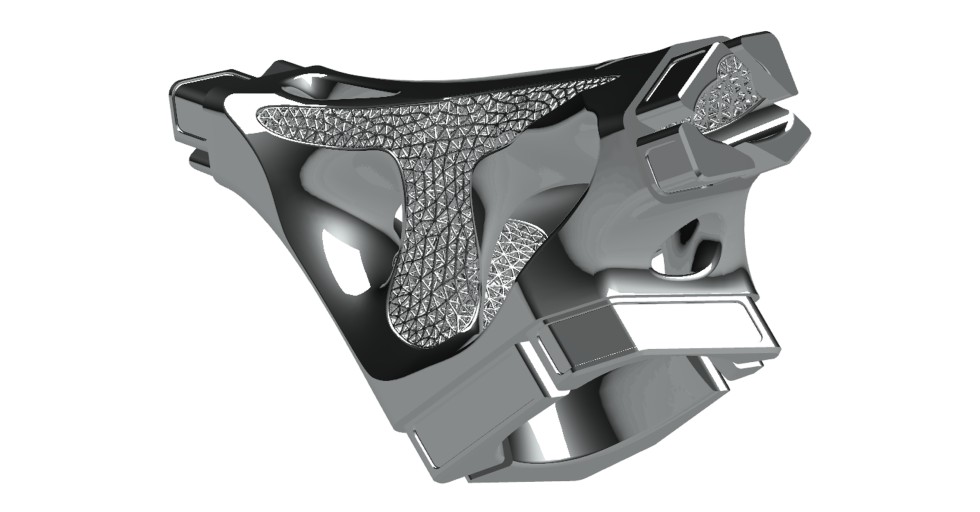
Picture 1. A detail with an applied lattice structure
Another new feature in NX for additive techniques is the texturing command. The tools available so far were only able to impose a flat texture representation on selected faces and use visual effects such as the bump mapping method.
The new functionality creates real 3D geometry based on the provided graphic file. Such model preparation is necessary for the printer to be able to produce a detail with applied texture
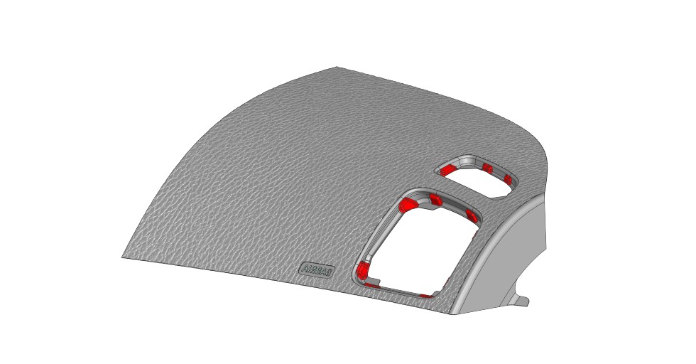
Picture 2. A detail with a 3D texture overlaid
Before starting the workspace configuration, the details must be properly oriented in relation to the printing axis. This task is particularly important because it affects the quality of parts, including distortions, surface roughness, local burns, and also the mechanical properties of details. Moreover, often the factors determining optimal orientation are mutually exclusive.
For this reason, NX offers a tool that allows you to find the best orientation minimizing the parameters: printing time, volume of support structures, volume of blown regions and the cross-sectional area of the layer. For more demanding users, a separate tool is available – Atlas 3D Sunata ™. In addition to the aforementioned parameters, it can also take into account thermal deformations of parts and find the orientation limiting them.
When starting the preparation of the printout, the components are inserted into the virtual working chamber of the printer. The user can do this by hand or using a pattern, but to make the most of the work space, also 3D nesting. It allows you to automatically arrange parts while locking the given degrees of freedom of elements. By increasing the packing density, the prints are less costly and faster, and with the additional consideration of the similar surface area of each sintered layer for some technologies, the quality of the products is improved.
Support structures can be generated for parts located in the working chamber. Using the automatic option, the program creates supports only for those regions that are inclined to the printing direction, exceeding the maximum overhang angle. The user can also perform these actions manually. Regardless of how these structures will be generated, the NX program offers a database containing 10 different types of supports, and it can also be extended with a base available in the printer and user-created supports.
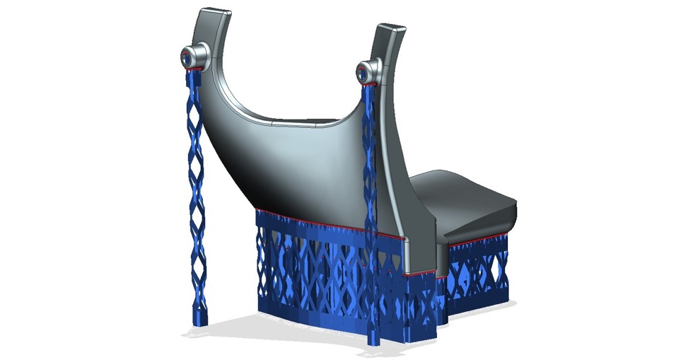
Rysunek 3. Struktury podporowe w NX
After completing the configuration, before sending the printout to the printer, NX allows you to simulate the printing process. It reduces the need for control prints to a minimum, significantly accelerating and reducing the cost of the process. As a result of the simulation, the user receives information about the part distortion and the temperature distribution during printing.
In addition, the probability of a collision with the machine recoater is checked. Importantly, based on the obtained data, the program is able to compensate for the distortions in the model geometry. This allows you to replace the original files with distorted in the opposite direction to the distortion after printing. As a result, the geometry of the finished elements is as close as possible to the original one from the CAD file.
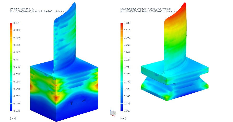
Rysunek 4. Symulacja procesu druku
Once the virtual working chamber of the printer is configured, the printout can be sent to the printer. This operation takes place directly in the NX program, which eliminates the need to export the model to intermediate formats (e.g. STL or 3MF) and import to external software. This is a significant simplification, and also streamlines the introduction of changes, as all operations that were performed before the print order are fully editable.
The data sent to the printer, i.e. the division into layers and the laser passes on each of them, can be checked before printing. Using the built-in patch browser, the user can check the course of the printer’s work and, if necessary, make the necessary modifications.
The tools available in the NX program described in this article close the process of model preparation and printing into one CAD/CAM/CAE system. The possibility of creating, editing and checking details, modeling innovative structures and configuring the printer chamber is extended by a range of simulation tools. They allow you to examine the properties of the printout, correctly orient it in the printer and obtain information about distortions and burns by simulating the print. By adding a direct connection to the printer, we get the only such comprehensive program on the market dedicated to 3D printing technology.


